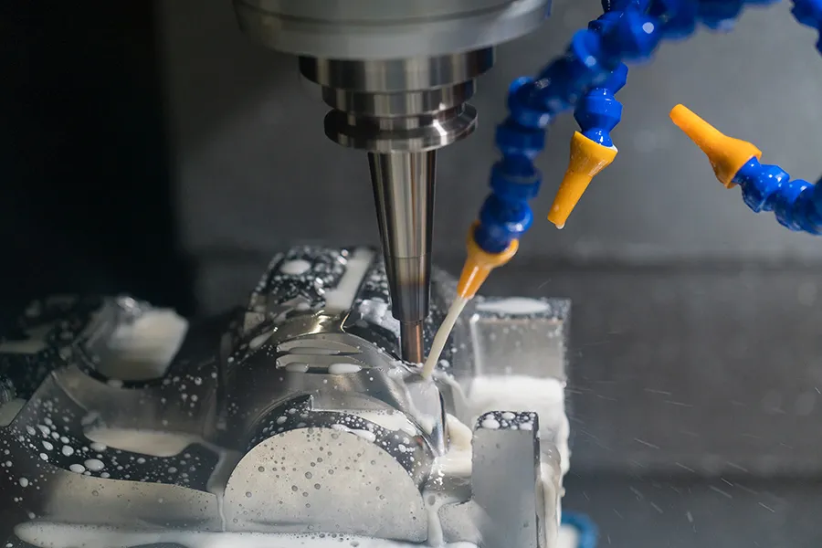
One of the biggest goals in manufacturing is “to do it in one shot”: put a piece of material in a machine tool, run a program, and end up with a perfectly finished part. Arguably more than any other process, 5 axis CNC machining, the use of CNC to move a part or cutting tool in five different axes simultaneously, gets us closer to the goal of “do it all in one go”. It can machine very complex parts, which is why five-axis machining is especially popular in aerospace. The five-axis can be fully processed and can realize one-time clamping, which can reduce the cost of clamping and reduce product scratches and bumps. Five-axis CNC machining is suitable for machining some multi-station holes and planes, and parts with high machining accuracy requirements, especially It is a part with strict requirements on shape machining accuracy. There are many benefits to using 5 axis CNC machining technology, as follows:
1. Simple setup: 5-axis CNC machine makes it possible to easily machine complex shapes in one setup. It doesn’t need to be set multiple times, which can lead to bugs. A single setup helps reduce setup and manufacturing time and increases productivity. In addition to shortening lead times, this processing technology also helps increase production and cash flow.
2. Faster cutting speed: Since 5 axis CNC machining allows simultaneous movement along both X and Y axes, you can use shorter, stronger tools. Using a shorter, stiffer cutting tool can help speed up the cut with minimal or negligible vibration.
3. Improve accuracy: The workpiece does not move during the 5 axis CNC machining process, which can achieve higher part accuracy.
4. Superior Finish: Shorter tools used in 5 axis CNC machining help achieve superior surface finish for better part quality.
5. Can machine complex parts: With this machining technology, you can manufacture extremely complex machine parts in less time and at lower cost. This is a great benefit for applications or prototypes running on a small scale.
Programming tips for 5 axis CNC machining:
Driving method: Common methods include rationalization (more intelligent), surface (setting parameters such as cutting direction step distance, cutting method), boundary, etc. After determining the drive method, select the drive geometry and select the drive geometry. Used to generate the first “virtual toolpath”, observe the plausibility of the toolpath, and then optimize it.
Projected Vectors: Describes how to first generate a virtual toolpath and then project it onto the workpiece geometry. The protrusions affect the quality of the final toolpath on the work surface, independent of the tool orientation. If the projection is not correct, the toolpath will be cluttered with twists and turns.
In general, the projected vector options are few and often selected, tool axis (tool path along the tool axis to project the tool surface direction), vertical screwdriver (drive geometry), specified vector, projection principle above. Easy to understand and work.
Tool axis: During processing, the tool position “walks” in the final tool path. The tool position can be divided into fixed tool axis, axial change, two-axis change, etc. The tool has many options.
With the exception of applications of straight lines, open area surfaces, or surfaces of revolution, each path of tool orientation changes direction, the tool pose becomes a straight line, and the tool path changes as the machining direction changes. This approach is limited if there is artifact interference.
It is best to use an enclosed area away from this point. This method is limited because each path of the tool pose has two directional changes, and the pose changes greatly
For vertical drive, the generation tool will always generate gestures vertically, depending on the selection. If it is a straight inclined plane, the tool posture is fixed, and if it is a curved surface, the tool posture will change accordingly. You cannot specify the tilt angle at any time. Interference occurs when the structure of the tool and workpiece cannot adjust the attitude of the tool. This method is limited.
Compared to the drive body, it is more flexible than the vertical drive body. When the machining surface is a curved surface, the attitude of the tool changes at any time during machining, and the roll angle can be specified. If the tool interferes with the workpiece structure, the roll angle can be adjusted to avoid
4 axes, perpendicular to the drive/Applying closed areas such as rotating body structures to the drive can generate motion throughout the cycle of the tool path and change the roll angle, rake angle, etc. The method is simple and convenient.
Drive the side edge, use the oblique edge tool side edge slanting wall, specify the side edge direction as “up (lift tool attitude)”, if the wall is a straight slope, the tool profile does not change, while the wall surface and the tool processing attitude change, pass Specifying the inclination angle can continuously change the attitude, and the method is more flexible.
Profile milling machines used to sharpen sloping straight walls with a known bottom will automatically find the sloping wall surface to be machined that cannot be sharpened (driven sharpening with a side edge). Flank drive is very similar to face mill generation similar to a single tool path, but you can use a transformation of multiple tool paths.
Finally, multi-axis programming is mainly based on the surface structure and processing requirements of the workpiece, using the model of the 5-axis machine tool to avoid interference with the workpiece, optimize the tool attitude and processing, and generate a reasonable tool path. Programming itself is not difficult to master, but it is not difficult to master the processing technology.

