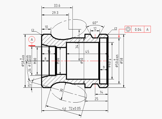
Modern CNC machining systems can interpret part geometry directly from 3D CAD files. It can be said that CNC lathe machining drawings are very important information and are widely used in the industry because they can improve the communication of technical requirements between engineers and machinists. This article will mainly introduce the importance of CNC lathe machining drawings.
CNC lathe processing is a high-precision and high-efficiency machine tool with digital information control system and tool displacement. CNC lathe is an effective way to solve the problems of large variety of aerospace product parts, small batch, complex structure, high precision and high degree of automation.
CNC lathe machining is a high-tech machining method for precision hardware parts. Various types of materials can be processed, such as 316, 304 stainless steel, carbon steel, zinc alloy, alloy steel, titanium alloy, alloy aluminum, iron, copper, plastic and other raw materials, and CNC lathes can also be processed into complex combinations of square and round shapes. structural parts.
Why is CNC lathe machining drawings still important?
Usually, when the CNC lathe is going to be process the 3D CAD model including the following content, the CNC lathe processing drawing will convey very important information:
- Threads (threads can be internal or external and can usually be put together)
- Tolerances with characteristics exceed the standard
- A single surface with specific surface treatment requirements (surface roughness, etc.)
CNC lathe processing drawings
The above requirements cannot be communicated in the 3D CAD file, even if the design does not include the above, when placing a CNC order, the operator is usually advised to use the 3D CAD file with the CNC lathe machining drawings. Typically, 3D CAD files are used to program CNC machines, and the graphics are used as references throughout the machining process. Most operators can also fabricate parts directly from CNC lathe drawings, and they usually prefer them to 3D CAD files because they have extensive CNC lathe machining experience and can quickly interpret part geometry, identify The main dimensions, functions and key features of the part make it easier and easier to assess the manufacturing cost of the part.
Analysis of CNC Lathe Machining Drawings
A typical CNC lathe machining drawing sheet includes the following parts: title block, isometric/picture view of the part, main orthographic view of the part, section or detail view.
The title bar of the CNC lathe machining drawing needs to contain basic information about the part, such as part name, material, surface treatment and color requirements and so on. Filling out this basic information is important because it informs the operator of the part’s function. The title block also contains other technical information, such as the scale of the CNC lathe machining drawings, the standards used for dimensioning and tolerances. It is recommended to add one or more 3D graphical views of the part to the drawing, as this allows the drawing to be seen at a glance.
Most information about part geometry is conveyed in the main orthographic view. is a 2D depiction of a 3D object, representing the exact shape of the part, viewed from one side of the bounding box at a time. Only the edges of the part are drawn this way to more clearly convey dimensions and features. For most parts, two or three orthogonal views are sufficient to accurately describe the entire geometry.
CNC lathe machining drawings
Section views can be used to show internal details of a part. The cut lines in the main orthographic view show the cross-section of the part, while the hatch pattern in the section view represents areas where material has been removed. CNC lathe machining drawings can have multiple profiles with two letters connecting each cut line to each profile (eg, AA, BB, etc.). The arrow of the cutting line indicates the direction we are looking.
Detail views are used to highlight complex or difficult-to-size areas of the main orthographic view. They are usually circular (offset placed to avoid confusion) and annotated with a single letter that links the detail view with the main figure (eg A, B, etc.).
This article mainly introduces the importance of CNC machining drawings. Through the article, we can understand that typical CNC lathe machining drawings include the following parts: title block, isometric/picture view of the part, main orthogonal view of the part, section view or partial view. If you want to know more about CNC lathes, you can follow us.
Related posts:
fabrication services
oem customized cnc machining
customized cnc machining turning steel parts
custom cnc machining aluminum parts

